NOTE: THIS WEBSITE IS NO LONGER MAINTAINED AND HAS BEEN MOVED TO ESTECH321.WORDPRESS.COM
Tutorials / Make a Simple NOT Gate
Print
Transistors are among the most important electronic components. They act like a switch operated by electricity, allowing one current to control whether or not another current can flow. In this tutorial, you’ll learn how to use one to make a simple NOT gate circuit. A NOT gate is a circuit that inverts an input. For example, if a light was connected to a power source through a simple switch, it would light when the switch was closed and go out when the switch was opened. However, a NOT gate makes the light do the opposite, turning on when the switch is open and off when the switch is closed.
Let’s look at the circuit diagram below. LED1 will be our reference light, turning on when the switch is closed and off when it’s open. LED2 is the inverted one. It will light when SW1 is open because it is permanently connected to +6V and ground. Once SW1 closes, power flows into the base of Q1. This allows current to flow between Q1’s collector and emitter, shorting R2 to ground and preventing the LED from receiving power.
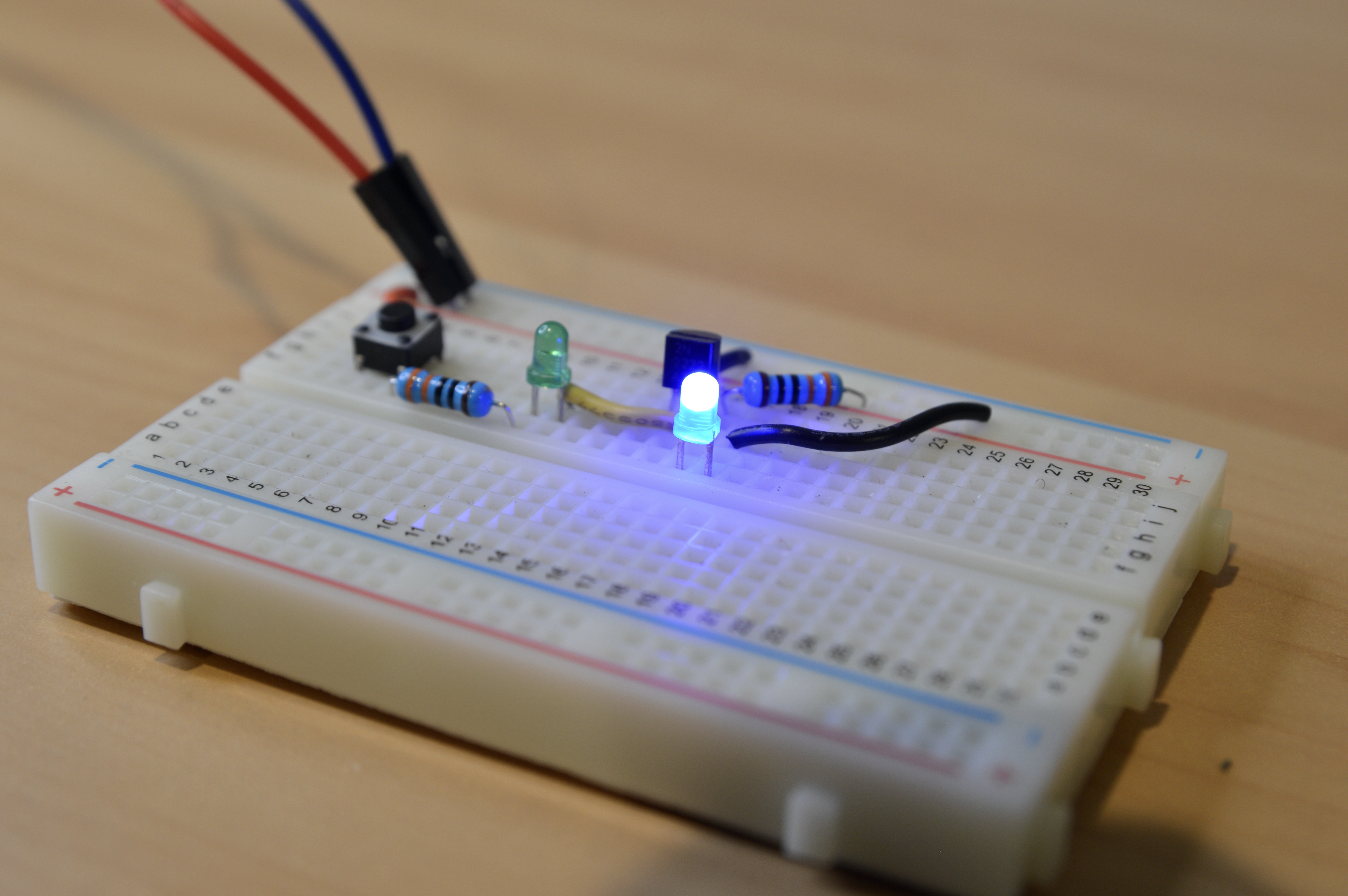
Try it out yourself! Grab a breadboard, some LEDs and resistors, a switch or button, a 6V power source, and a 2N2222A transistor. Carefully follow the circuit diagram and double-check the placement of your components once you’re done. Then plug your power supply or batteries into the circuit and test out your NOT gate! If it doesn’t work, first ensure you’ve connected everything properly. Then test your power source with a multimeter to make sure it’s 6 volts. It’s also worth flipping your LEDs around in case you got the wrong polarity or replacing them in case they’re dead. If you’re using a pushbutton, try flipping it around in different positions, as well. If all else fails, you can replace the transistor if it’s dead.
Congratulations! You just built a circuit that inverts an input and shows it visually through the use of LEDs.